This project aims to build a robust control platform for an open-source 3D printable robotic arm using ROS.
The Motivation
The BCN3D Moveo is a widely used open-source design for a 3D printable 5DOF robotic manipulator, and it costs about $400 to build. It is mechanically well-designed, though it lacks a platform for feedback control. In fact, there are currently no robotic arms at this low of a price tag that offer an open-source platform for feedback control development.
Currently, the standard control paradigm is G-code, which is a procedural instruction set used for 3D printing. G-code lends itself to predefined motions of the robotic arm, but it's not really useful for feedback control (i.e. using data from sensors on the robotic arm to make real-time decisions regarding movement). A platform for robust feedback control would allow you to do things like use perception and an IMU to control movements, or use force sensors to control grasps – there's an incredible amount of potential here. Through this project, I hope to make the Moveo a powerful tool for exploring complex control concepts at the forefront of robotics.
The Solution
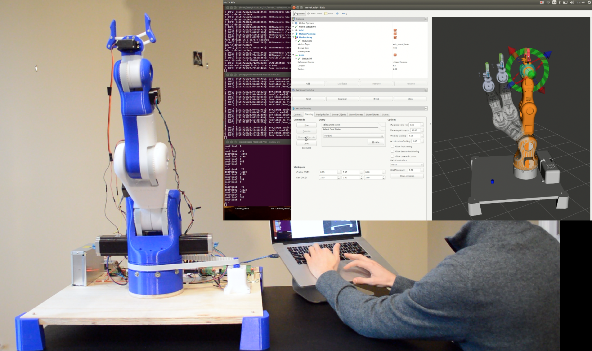
This project initially involved physically printing and constructing the robotic arm. Then, I needed to figure out three major things: simulating the robot, controlling the real robot, and coming up with an interface between the simulation and the real robot. With these three components, you have an appropriate platform for testing and development of control algorithms on a robotic arm. For example, you can test and debug proprietary algorithms on the simulation, and then implement those algorithms on the real robot through an interface. The interface serves as a communication scheme between the simulation and the real robot.
A detailed, technical walkthrough of how to accomplish all of this, along with code, is provided here. A video depicting what I've done is shown below. This project has already gained some steam on Github, and people are starting to adopt this method of control for their Moveo robotic arms.
The following is meant to be a higher level description of the work done thus far.
Simulation of the Robot
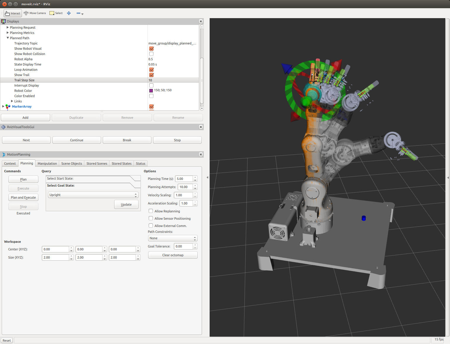
First, I used Solidworks to create a URDF (Unified Robotic Description File) of the Moveo. The URDF details the configuration of joints, links, textures, physical constraints, etc. necessary to build a 3D rendering in simulation softwares such as RVIZ and Gazebo. Then, I used this URDF to configure the Moveo with Moveit – Moveit brings motion planning capability to the robot in simulation. Using Moveit, it is possible to plan and execute trajectories using a variety of motion planning algorithms. Here is an image of the simulation in action with motion planning.
Controlling the Real Robot
For hardware on the robot, I used an Arduino Mega 2560 along with a RAMPS 1.4 (standard hardware in open source 3D printer control, as well as the design specified for Moveo). All joints are actuated with stepper motors except the parallel-jaw gripper, which is actuated with a servo. In order to control the robotic arm, I needed to write Arduino firmware that actuated the motors and servo. I used an external library called AccelStepper for motion control of the stepper motors. The next step was to build an interface that would allow communication between the simulation and the real robot. An aerial sketch of the wiring schematic and layout for my robot is shown below.

Building the Interface
The objective of the interface here was to provide a scheme for real-time communication between the simulation and real robot. Using ROS, this was fairly straightforward – create rostopics that host the information to be transmitted/received, and both the simulation and Arduino firmware can publish or subscribe to those rostopics in real-time. The first natural step to implement this interface, in my opinion, was the following: move the robot in simulation, and have the real robot echo that movement in real-time. To do this, I created a rosnode that converted the rotation (in degrees) of each joint on the simulated arm to steps. These steps were the actual number of steps necessary to move the robotic arm to the desired position. The conversion from degrees in simulation to steps on the real robot required calibration, but turned out to be fairly accurate. Then, to send the steps data to the Arduino, I wrote a custom ROS message which structured the steps data. I wrote a rostopic called /joint_steps, along with a publisher from the simulation side and a subscriber on the Arduino firmware. This way, whenever a motion was executed in simulation, the motion was echoed on the real robot.
**Once again, a detailed, technical walkthrough of how to accomplish all of this is provided here.
Next Steps
Next on the list is equipping additional sensors for the robotic arm, such as making motion control decisions based on data from monocular images, IMU, RGBD sensors, and force sensors. I am currently working to update this platform so that it becomes a powerful tool for robotics developers, at a low cost.
Applications
Object-Specific Pick and Place
Here is an example demonstrating the potential of this platform. Using real-time object recognition from a monocular image (ordinary webcam) in conjunction with this platform, we can perform 'pick and place' trajectories that are specific to the recognized object. As is, this type of application could be useful for sorting objects in industrial automation. Below is a video that shows this useful application in action.